By, Tony Armstrong, Analog Devices, Inc.
At the medium-to-low end of the power spectrum, there are modest power conversion requirements, such as those commonly found in Internet of Things (IoT) equipment, that necessitate the use of power conversion ICs that deal with modest levels of current. These are usually in the range of hundreds of milliamps of current, but that amount can be higher if there are peak power demands that are needed by an onboard power amplifier for the transmission of data or video. Accordingly, the proliferation of wireless sensors supporting the numerous IoT devices has increased the demand for small, compact, and efficient power converters tailored to space and thermal constrained device form factors.
However, unlike many other applications, many industrial and medical products typically have much higher standards for reliability, form factor, and robustness. As you would expect, much of the design burden falls on the power system and its associated support components. Industrial and even medical IoT products must operate properly and switch seamlessly between a couple of power sources such as the ac mains outlet and a battery backup. Furthermore, great lengths must be taken to protect against faults, while also maximizing operating time when it is powered from batteries to ensure that normal system operation is reliable regardless of what power source is present. Accordingly, the internal power conversion architecture used within these systems need to be robust, be compact, and require minimal heat sinking.
Power Supply Design Considerations
It is not unusual for an industrial IoT system designer to use linear regulators in a system that incorporates wireless transmission capability. The primary reason being that it minimizes EMI and noise emissions. Nevertheless, although switching regulators generate more noise than linear regulators, their efficiency is far superior. Noise and EMI levels have proven to be manageable in many sensitive applications if the switcher behaves predictably. If a switching regulator switches at a constant frequency in normal mode, and the switching edges are clean and predictable with no overshoot or high frequency ringing, then EMI is minimized. Moreover, a small package size and high operating frequency can provide a small, tight layout, which minimizes EMI radiation. Furthermore, if the regulator can be used with low ESR ceramic capacitors, both input and output voltage ripple, which are additional sources of noise in the system, can be minimized.
It is common for the main input power to today’s industrial and medical IoT devices to be a 24 V or 12 V dc source from an external ac-to-dc adapter and/or battery bank. This voltage is then further reduced to either 5 V and/or 3.x V rails using synchronous buck converters. Nevertheless, the number of internal postregulated power rails in these medical IoT devices has increased, while operating voltages have continued to decrease. Thus, many of these systems still require 3.x V, 2.x V, or 1.x V rails for powering low power sensors, memory, microcontroller cores, input/output, and logic circuitry. Nevertheless, the internal power amplifier used for data transmission can require a 12 V rail with up to 0.8 A of current capability to transmit any recorded data to a remote centralized hub.
Traditionally, this 12 V rail has been supplied by step-up switching regulators and required specialized switch-mode power supply design know how, as well as a large solution footprint on the printed circuit board (PCB).
A New Compact Boost Converter
Analog Devices’ µModule® (micromodule) products are complete system-in-package (SiP) solutions that minimize design time and solve the common problems of board space and density issues commonly found in industrial and medical systems. These µModule products are complete power management solutions with integrated dc-to-dc controllers, power transistors, input and output capacitors, compensation components, and inductor within a compact, surface-mount BGA or LGA package. Designing with ADI’s µModule products can reduce the amount of time needed to complete the design process by up to 50%, depending on the complexity of the design. The µModule family transfers the design burden of component selection, optimization, and layout from designer to the device, which shortens the overall design time and system troubleshooting, as well as ultimately improving time to market.
Furthermore, ADI’s µModule solutions integrate key components commonly used in discrete power, signal chain, and isolated designs within a compact, IC-like form factor. Supported by ADI’s rigorous testing and high reliability processes, the µModule product portfolio simplifies the design and layout of power conversion designs.
The µModule family of products embraces a wide range of applications including point of load regulators, battery chargers, LED drivers, power system management (PMBus digitally managed power supplies), isolated converters, battery chargers, and LED drivers. As highly integrated solutions with PCB Gerber files available for every device, µModule power products address time and space constraints while delivering a high efficiency, reliable and, with select products, low EMI solution compliant with EN 55022 Class B standards.
As design resources become stretched by increased system complexity and shortened design cycles, the focus falls on development of the key intellectual property of the system. This often means neglecting the power supply until late in the development cycle. With little time and perhaps limited specialist power design resources, there is pressure to come up with a high efficiency solution with the smallest possible footprint, while potentially utilizing the underside of the PCB as well for maximum space utilization.
This is where the μModule regulator provides an ideal answer. The concept is complex on the inside, simple on the outside—the efficiency of a switching regulator and the design simplicity of a linear regulator. Careful design, PCB layout, and component selection are very important in the design of a switching regulator and many experienced designers have smelt the distinctive aroma of burning circuit board in the earlier days of their career. When time is short or power supply design experience is limited, the ready-made μModule regulator saves time and reduces risk.
One recent example from the ADI µModule family is the LTM4661 synchronous step-up µModule regulator, which is available in a 6.25 mm × 6.25 mm × 2.42 mm BGA package. Included in the package are the switching controller, power FETs, inductor, and all support components. Operating over an input range of 1.8 V to 5.5 V, it can regulate and output voltage of 2.5 V to 15 V, and is set with a single external resistor. Only a bulk input and output capacitor are needed.
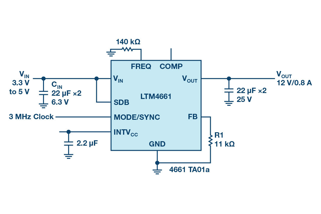
The LTM4661 is efficient and can deliver efficiencies of greater than 87% when stepping up from a 3.3 V input to a 12 V output. See the Figure 2 efficiency curve.

Figure 3 shows the measured thermal picture of the LTM4661 running from a 3.3 V input to 12 V at 800 mA dc current with 200 LFM airflow and no heat sink.

Conclusion
The deployment of IoT equipment has exploded in recent years and includes a wide variety of products for the military and industrial application spaces. A new wave of products, including sensor-filled medical and scientific instrumentation, has been a key market driver in recent years and is now starting to see signs of significant growth. At the same time, the space and thermal design constraints of these systems has necessitated a new class of power converters that can deliver the necessary performance metrics of small, compact, and thermally efficient footprints to power the internal circuits, such as the power amplifier. Fortunately, devices such as the recently released LTM4661 step-up µModule regulator elevates the power supply designer’s task.
Finally, using µModule regulators make sense in these types of applications since they can significantly reduce debug time and allow for greater board area usage. This reduces infrastructure costs, as well as the total cost of ownership over the life of the product.