By Cathal Sheehan, Bourns Electronics, and Nicola O’Byrne, Analog Devices
Current-sense resistors are readily found in motor control system design to benefit from new digital isolation technologies. These technologies offer higher reliability, based on the component-level standard IEC 60747-17, which specifies the performance, test and certification requirements for capacitive and magnetically-coupled isolators. Other benefits include faster loop responses, allowing for integrated overcurrent protection, and narrower dead times, enabling smoother output voltages that, in turn, provide better torque control.
Update on Isolation Standards
Designers of motor drives must comply with international standards for isolation for several reasons:
– To prevent electrical noise from the ground connection of a high-power circuit being induced onto a low-power signal line;
– To provide electrical safety for end users by preventing dangerous voltages and currents from transferring to a benign, low-voltage environment.
The IEC 61010-1 Edition 3 standard specifies that system-level designers must be aware of distances between conductors, through air (clearance) and over surfaces (creepage). It also stipulates that they must know the separation between conductors and metallic parts in potting, moulding compounds and thin-film insulation. A designer should ensure that the chosen components guarantee a certain level of safety if they are being used on IEC61010-1-compliant systems. According to the standard IEC 60747-17, the reinforced isolation is tested using the industry-accepted time-dependent dielectric breakdown (TDDB) analysis, which then helps to extrapolate the device’s lifespan and continuous working voltage (VIORM).
While IEC 60747-17 (DIN V VDE V 0884-11) was adopted to specifically define insulation using inductive and capacitive technologies, the well-established IEC 60747-5-5 standard was used to define the insulation using optocoupler technologies. However, IEC 60747-5-5 does not specify the TDDB analysis to determine the continuous working voltage or lifetime. It relies on the partial discharge voltage test to establish the working voltage but does not define the working lifetime of a device. Hence, inductive and capacitive technologies have minimum-rated lifetime of 37.5 years, while there’s no definition for optocoupler-based isolators.
The non-optocoupler-based standards will gain more acceptance over time, since they offer greater security and longer operating lifespans.
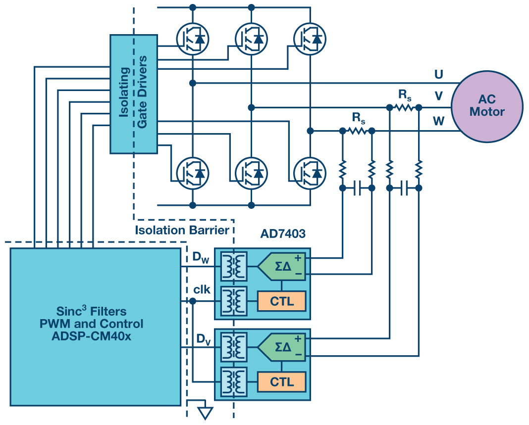
Figure 1: Block diagram of a three-phase motor drive with digital isolation and current-sense resistors
A Typical System with Reinforced Isolation
Figure 1 shows a typical three-phase permanent magnet motor drive that uses sense resistors for measuring winding current and with feedback through the Analog Devices’s AD7403 isolated Σ-Δ modulator and a sinc3 filter. The AD7403 uses a single second-order modulator digitising circuit that converts the analogue signal from the sense resistor into an isolated single-bit pulse stream, which scales according to the full-scale input voltage range. The sinc3 filter then extracts the average value of the current, whilst eliminating noise created by inverter switching. It can store in memory a 16-bit integer representing the current, and at the same time compare the number with a reference representing the current limits, sending an alert via a separate pin during overload conditions. The use of shorter filters for overload monitoring, in parallel with the measurement filter, allows for reduced alert latencies.
The AD7403 has reinforced isolation allowing the current-sense resistor voltage to be measured directly by the modulator with no extra components, apart from a simple, discrete, low-pass filter, comprising a resistor and a capacitor. The specified maximum operating voltage of the modulator is ±250mV, which requires that the resistance value of the current-sense resistor be lower than 250mV/IMAX.
Choosing the Right Resistor
Resistance Drift with Temperature
Considering the AD7403’s output is a 16-bit number, the potential accuracy of the current measurement is limited not by the ADC conversion but by the voltage reading itself. The drift of the resistance with temperature will vary depending on the resistor element material, as well as its power rating and the component’s actual physical size.
Special-alloy resistive elements like nickel, copper and manganese are the most accurate materials used for current-sensing applications; they have parabolic resistance drift curves (Figure 2). The figure also shows the upper and lower limits of resistance drift of a Bourns’s model CSS4J-4026R resistor, corresponding to a temperature coefficient of 50ppm/°C. This gap is caused by the resistor’s copper terminals, which increase drift due to the high TCR of copper (4000ppm/°C). Bourns’s model CST0612 series is a 1W, 4-terminal resistor made from a special alloy. It measures 3.2mm × 1.65mm, has a TCR of ±100ppm/°C, and the difference in TCR between models CST0612 and CSS4J-4026R can be explained by the proportion of copper with respect to the resistive element. The additional copper with its low thermal resistance helps the component absorb high power without overheating. This example demonstrates the trade-off between component size, its power rating and drift in resistance value over temperature.
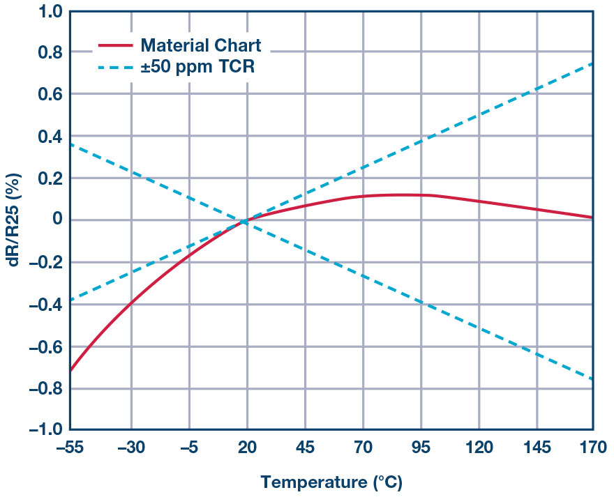
Figure 2. Parabolic TCR curve of a Bourns model CSS4J-4026R current-sense resistor
Resistance Drift Calculation
Let us use Bourns’s part number CSS4J-4026R-L500F for calculating the resistance drift at full power and ambient temperature of 70°C. CSS4J-4026R-L500F is a 0.5mΩ (±1%) sense resistor rated to 5W, at a maximum ambient temperature of 130°C. The device de-rates from 100% power to 0W at 170°C, which makes its thermal resistance 8°C/W. At full power and 70°C, we can expect the component surface temperature to reach 110°C (70°C + 8 × 5°C). The drift in resistance at 110°C can be taken from Figure 3, which is +0.45% of the nominal value at 25°C. The absolute tolerance is ±1% and, therefore, the current measurement’s accuracy will be a maximum of +1.45%.
Overloads
Motor drives will experience short circuits from time to time, and the current-sense resistor must be able to handle short overloads without being damaged. Using model CST0612 current-sense resistor from Bourns as an example, it is possible to calculate the mass of this component from the material datasheet on the Bourns’s website at 0.0132g. Alternatively, it can be calculated from the dimensions and density of copper and alloys (8.4/cm3). The rate of rise in temperature can be calculated with:

where P is power (W), m is the component’s mass (g) and C is the specific heat capacity of the metal alloy.
An overload of 50A in 1mΩ resistance would create a 462°C per second temperature slew rate. Assuming steady-state temperature of 50°C, the width of the short-circuit period cannot exceed 0.22s, which can be extended by increasing the overall mass through copper plating on the circuit board.
A thicker, larger part such as CSS4J-4026 with a mass of 0.371 g would have a temperature slew rate of 16.5°C per second, given the same overload. Assuming the component had a surface temperature of 100°C, it would handle high energy up to four seconds before the surface temperature reached the maximum allowed of 170°C.
Appropriate Resistance Value
The AD7403 has a full-scale input of ±250mV from the resistor. The designer can compensate for lower voltages by adjusting the scaling factor.
Confidence Factor
According to IEC60747-17, the minimum lifetime of a digital isolator rated to reinforced isolation should be 37.5 years. While there is no such reference for more traditional optocoupler technologies, designers should feel more confident about working with digitally-isolated systems in the future. Current-sense resistors made using special alloys have low resistance drift over temperature and produce output voltages that can be read with an adjustable scaling factor by an isolated Σ-Δ modulator, such as those using Analog Devices’s iCoupler technology. The accuracy of the current measurement will depend on the temperature of the resistor, which in turn depends on the power as a proportion of the power rating, as well as the ambient temperature.