By Anritsu EMEA design team
Due to growing information exchange, faster communications standards such as 100, 200, 400GbE and OTN, PCIe Gen4, USB3.1 and Thunderbolt 3 are now in the fore for high-speed transmission and processing of large data volumes.
Telecommunication technologies for implementing high-speed, large-volume transfers are centred on PAM (Pulse Amplitude Modulation) and NRZ (Non-Return-to-Zero) signal methods, nowadays also required for data interconnection between equipment and their internal modules or components. But, prior to implementation, these technologies undergo thorough evaluations and testing, which require measurement equipment.
NRZ and PAM
NRZ is the most used binary format, composed of two levels, 1 or 0. It has come a long way from where it started, from a low-level kbits/s rates to now almost reaching 64Gbits; there are 100G modules consisting of four channels 25/28G.
PAM methods are being implemented throughout the telecoms industry. Next-generation 200 and 400Gbits/s transmission methods, defined by IEEE802.3bj, 100GBase-KP4 and IEEE802.3bs, increase transmission capacity compared to the conventional NRZ method, without increasing the symbol rate. In PAM-4 signalling, instead of transferring 1 bit at one of two levels of 0 or 1 in one time-slot as in NRZ signalling, two bits of data are transferred at four levels in one time-slot. In PAM-8 signalling, three bits of data are transferred at eight levels in one time-slot.
PAM has the advantage of increasing the data transfer capacity without increasing the signal symbol rate, but, conversely, since the voltage level of each signal in one time-slot becomes lower, it has the disadvantage of a poorer signal to noise ratio (SNR).
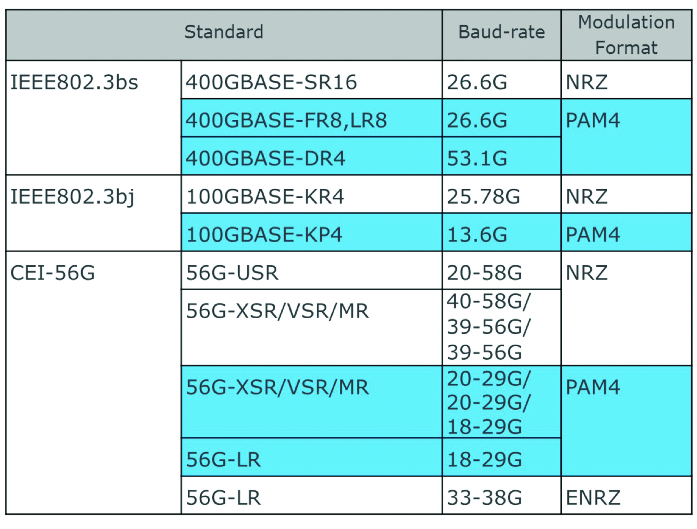
Figure 1: Transmission capacities by standard
Tests Considerations
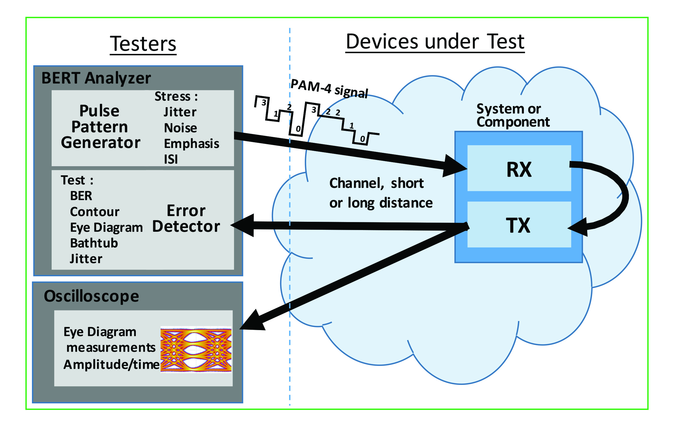
Whether for electrical or optical signals, NRZ or PAM-4, a general diagram can be drawn to represent a transmission channel under test.

Figure 2. Transmission channel under test
All transmission links must be tested to confirm that data is correctly transmitted, and that the network and its equipment can be shared in two parts, one for transmission and the other for reception of signals. In receiver equipment (denoted Rx in Figure 2), it is necessary to apply a signal source to test its ability to detect it correctly. For transmitter equipment (denoted Tx in Figure 2), tests can be performed with an oscilloscope and must be validated by counting errors using a BERT (Bit Error Rate Tester). To allow a full test of the input/output of the link, whether testing on a short- or long-distance link, a configuration called Loopback, where Rx is connected to Tx, is often used. In Figure 2, for testing optical signals, equipment such as an optical modulator or demodulator will be added.
For testing digital communications, one important test system for tracking the digital source is a Pulse Pattern Generator (PPG); it gives an image of the signal as it will be transmitted in the real network, but must have the specifications (NRZ, PAM, electrical, optical) required to conduct the tests. This signal is either the most ideal possible to measure the defects throughout the transmission chain, or to test the component Rx, the signal is intentionally disturbed to reproduce network defaults. The other alternative is to put an Error Detector (ED), which will replace the Rx receiver so we can measure the transmission error rate.
The Pulse Pattern Generator (PPG)
High signal quality at the generator output is a pre-requisite and, where possible, good specifications such as amplitude, rise and fall time, intrinsic jitter and noise among others, should be provided. These performance variables are not easy to get, especially for very high bit rates; for example, for PAM-4, high amplitude, low noise and good linearity are all required. Also, because module- or channel-under-test are often differential, the PPG outputs should be differential, too. Currently an Arbitrary Waveform Generator (AWG) is not able to provide as high a quality signal as a PPG.
Depending on the standards of the different binary sequences used, the PPG should be able to follow all these recommendations; for example, the QPRBS13 for the CEI-56G and the PRBS31Q for the IEE 200G and 400G.
Several PPG channels can be required for the tests, and a solution such as Anritsu’s MP1900A supports up to 16 synchronised channels, with adjustable skew. Crosstalk test, for example, uses at least two channels, whereas PAM-4, PAM-8 or multiplexing for higher bit-rates require a combination of channels.
Another function is the Stress Test: the PPG is able to add defaults and improvements to the signal as if on a true channel; this transformed signal will then stress the device or system under test. These signal transformation specifications follow standards such as IEC56G or IEEE 802.3. Capabilities required of them include amplitude adjustment and noise, frequency response and deviation, jitter, pre-emphasis, embedding and de-embedding of networks, and more. Equipment like Anritusu’s MP1900A signal quality analyser should be able to generate all the stresses required by these standards.
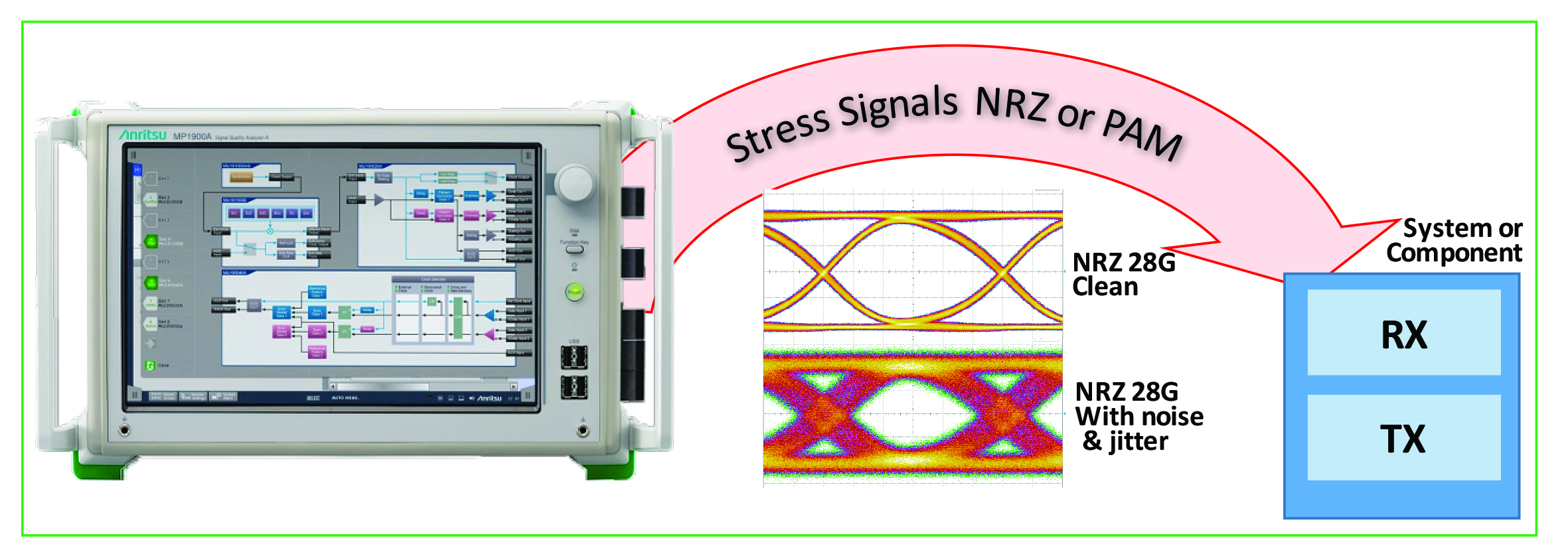
Figure 3: MP1900A generates required signals for stress tests
Emphasising the signal is an important function of the transmitter in a telecommunications system, so the PPG must reproduce this function. The MP1900A can adjust the frequency response by using 10 taps, a function that can be increased in three modes: “manual”, where the user manually adjusts the taps; “emulation”, where 2 or 4 ports S-parameters are used to adjust the taps – a very powerful tool for embedding or de-embedding a network into the channel; and “ISI”, which is a slope with two points at Nyquist and ½ Nyquist frequencies. In these three modes, defined frequency responses can be adjusted to follow standards such as the IEC 25G/28G.

Figure 4: Three modes for adjusting defined frequency responses
Error Detector (ED)
The capabilities of the ED are determined by its sensitivity to detect and measure the signal at a given bit-rate, for example a signal of 10mVp-p with a PRBS31 at 28Gb/s for a BER equal to 0 errors; this signal could be NRZ or PAM-4.
To measure a signal, the ED needs a clock, which can be provided externally, so data and clock signals are connected to the ED, or a CDR (clock data recovery) is used, allowing data to be extracted. In the second instance it is better if the CDR is integrated into the ED, which reduces measurement errors caused by cable length.

Figure 5. Integrated equalisation with the MP1900A
For 25/28G standards, equalisation is required in the transmission channel. This feature is integrated into the ED of the MP1900A to reproduce the same configuration as the system. In Figure 5, the eye of signal at the output of equaliser is open and can be transmitted without errors.
For PAM-4 detection Anritsu offers two solutions, either tests for the three levels are done sequentially and automatically, in which case one ED is sufficient; alternatively, measure the signal in real time with a PAM-4 demodulator and two EDs.
In addition to the basic test, it is critical the ED measures the BER, but other tests as contour, eye diagram, eye margins and bathtub can also be made. These measurements are based on BER, depending on the amplitude and phase thresholds. Another important variable is jitter tolerance; in this case, for jitter generation and testing, the PPG and the ED are enabled to do automatic test.
New Generation for the BERT
Many things have changed with the latest generation of BERT testers. Not only are rates increasing to 64Gbauds for electronics, but these testers now need to go beyond just basic testing to count the number of errors.
The latest testers, known as Signal Quality Analysers (SQAs), are able to generate or analyse elaborate function signals. This equipment integrates functions such as stress testing and signal integrity and allows measurements against defined standards. Also, the relationship between datacom and telecom means that the need to conduct tests using SQAs can also relate to standards such as PCIe, Thunderbolt or USB.
The Anritsu MP1900A analyser is an SQA used for research and development of network components and systems. Another Anritsu tester, the MP2110A, integrates a BERT and an oscilloscope, and is used to produce 25 and 28G devices.